Difference between revisions of "Remote Disassembled"
Ezra pound (talk | contribs) |
Ezra pound (talk | contribs) |
||
| (8 intermediate revisions by the same user not shown) | |||
| Line 2: | Line 2: | ||
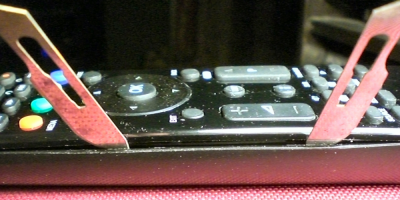
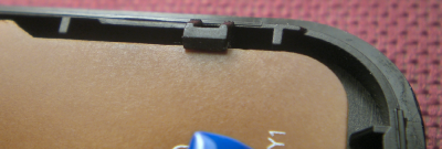
[[File:rem01.png|400px|thumb|right|'''Photo 2 - First 2 lugs 'popped'''']] | [[File:rem01.png|400px|thumb|right|'''Photo 2 - First 2 lugs 'popped'''']] | ||
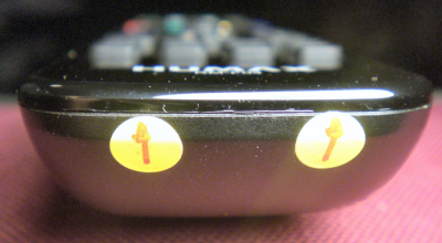
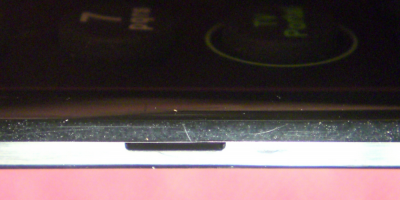
[[File:rem02.png|400px|thumb|right|'''Photo 3 - Battery end lugs''']] | [[File:rem02.png|400px|thumb|right|'''Photo 3 - Battery end lugs''']] | ||
| + | [[File:remote-pad.png|400px|thumb|right|'''Photo 10 - Before and after new key pads''']] | ||
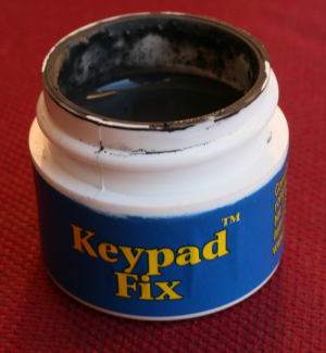
| + | [[File:keypadfix.png|300px|thumb|right|'''Photo 10a - Conductive paint''']] | ||
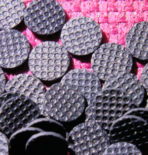
| + | [[File:pads.png|300px|thumb|right|'''Photo 10b - Replacement Pads''']] | ||
| + | |||
| + | |||
'''Background''' | '''Background''' | ||
| Line 8: | Line 13: | ||
You may also be just curious as to what is inside, Users have been known to disassemble their products for this very reason | You may also be just curious as to what is inside, Users have been known to disassemble their products for this very reason | ||
| + | |||
| + | |||
'''Warning''' | '''Warning''' | ||
| − | The RM-F04 Remote is not held together with screws, It is ‘Snapped’ together which make it quite difficult to take apart, It is not recommended that you | + | The RM-F04 Remote is not held together with screws, It is ‘Snapped’ together which make it quite difficult to take apart, It is not recommended that you disassemble your Remote unless there is a very good reason, e.g. it has stopped working. There is a real possibility that the case could be damaged |
| + | |||
| + | |||
'''Disassembly''' | '''Disassembly''' | ||
| Line 17: | Line 26: | ||
Remove the batteries and replace the cover, The case is held together with 12 ‘snap fit lug + Barbs’ (Photos 6 + 7), 5 on each long side and 2 at the battery end, The locations of the 5 side lugs are shown in Photo 1. The only tools required for the disassembly are two thin metal objects, I used two No. 22 scalpel blades (0.4mm thick), Although it is possible to use a thicker tool it will inevitably damage the case as the gap between the two halves of the case is very small. | Remove the batteries and replace the cover, The case is held together with 12 ‘snap fit lug + Barbs’ (Photos 6 + 7), 5 on each long side and 2 at the battery end, The locations of the 5 side lugs are shown in Photo 1. The only tools required for the disassembly are two thin metal objects, I used two No. 22 scalpel blades (0.4mm thick), Although it is possible to use a thicker tool it will inevitably damage the case as the gap between the two halves of the case is very small. | ||
| − | Locate a centre lug on a long side using photo 1 and insert a | + | Locate a centre lug on a long side using photo 1 and insert a scalpel blade at that point, leaver the bottom half of the case outwards and a ‘click’ should be heard as the barb disengages, Keep this scalpel in place while you work on the next lug towards the battery end, Do the same procedure on the second lug, Photo 2 shows two blades in place, It should be safe to remove the blades now. |
Disengage the last side lug at the battery end, Now locate the battery end lug (Photo 3) nearest to the lugs already opened and open it, Followed by the second battery and lug. | Disengage the last side lug at the battery end, Now locate the battery end lug (Photo 3) nearest to the lugs already opened and open it, Followed by the second battery and lug. | ||
| Line 28: | Line 37: | ||
Next use Methylated Spirits and a cotton bud (do not use an abrasive), to clean the round ‘Waffles’ on the underside of the buttons Photo 9 | Next use Methylated Spirits and a cotton bud (do not use an abrasive), to clean the round ‘Waffles’ on the underside of the buttons Photo 9 | ||
| + | |||
| + | |||
| + | |||
| + | '''Repair''' | ||
| + | |||
| + | As remotes get older the 'Waffles' (Photo 9) tend to lose their conductivity and no amount of cleaning will restore this, one solution is to attach aluminium foil to double sided sticky tape and then, using a paper punch, make circular sticky pads that can be stuck on top of the waffle. '''Note''' the repair shown in photo 10 is on a Philips product, but the principle applies to Humax remotes | ||
| + | |||
| + | An alternative to aluminium foil is conductive paint, one product is Keypad fix (Photo 10a), a liquid rubber solution that sets to form a new conductive surface, for a longer term fix, you can purchase replacement 'pads' (photo 10b) which provide a conductive block rather than a conductive surface, attach using clear silicon rubber NOT super glue | ||
| + | |||
'''Re-Assembly''' | '''Re-Assembly''' | ||
| Line 33: | Line 51: | ||
Clip PCB back into place, Then Hook the two halves of the case back together at the non Battery end and then snap all other lugs into place | Clip PCB back into place, Then Hook the two halves of the case back together at the non Battery end and then snap all other lugs into place | ||
| − | {| border=" | + | |
| + | |||
| + | |||
| + | |||
| + | {| border="0" | ||
|- | |- | ||
![[File:rem05.png|400px|thumb|right|Photo 4 - PCB under lug]] | ![[File:rem05.png|400px|thumb|right|Photo 4 - PCB under lug]] | ||
| Line 44: | Line 66: | ||
![[File:rem09.png|400px|thumb|right|Photo 9 - Button 'Waffles']] | ![[File:rem09.png|400px|thumb|right|Photo 9 - Button 'Waffles']] | ||
|- | |- | ||
| − | ![[File:rem06.png|400px|thumb|right|Photo | + | ![[File:rem06.png|400px|thumb|right|Photo 11 - Full PCB]] |
| − | ![[File:rem08.png|400px|thumb|right|Photo | + | ![[File:rem08.png|400px|thumb|right|Photo 12 - Rear of Buttons]] |
|- | |- | ||
| − | ![[File:rem12.png|400px|thumb|right|Photo | + | ![[File:rem12.png|400px|thumb|right|Photo 13 - Battery side of PCB]] |
| − | ![[File:rem11.png|400px|thumb|right|Photo | + | ![[File:rem11.png|400px|thumb|right|Photo 14 - Top side of Buttons]] |
|- | |- | ||
| − | ![[File:rem13.png|400px|thumb|right|Photo | + | ![[File:rem13.png|400px|thumb|right|Photo 15 - Back of Case (Inner)]] |
| − | ![[File:rem10.png|400px|thumb|right|Photo | + | ![[File:rem10.png|400px|thumb|right|Photo 16 - Top of case (Inner)]] |
|} | |} | ||
Latest revision as of 11:37, 10 August 2019
Background
The RM-F04 Remote Control supplied with the Humax HDR FOX T2 and Humax HD FOX T2 may need disassembling for various reasons, The main reason being that the Remote becomes unresponsive to key presses, even with new batteries.
You may also be just curious as to what is inside, Users have been known to disassemble their products for this very reason
Warning
The RM-F04 Remote is not held together with screws, It is ‘Snapped’ together which make it quite difficult to take apart, It is not recommended that you disassemble your Remote unless there is a very good reason, e.g. it has stopped working. There is a real possibility that the case could be damaged
Disassembly
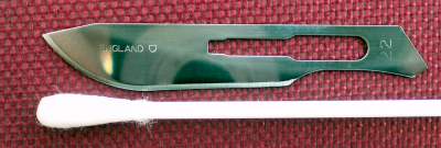
Remove the batteries and replace the cover, The case is held together with 12 ‘snap fit lug + Barbs’ (Photos 6 + 7), 5 on each long side and 2 at the battery end, The locations of the 5 side lugs are shown in Photo 1. The only tools required for the disassembly are two thin metal objects, I used two No. 22 scalpel blades (0.4mm thick), Although it is possible to use a thicker tool it will inevitably damage the case as the gap between the two halves of the case is very small.
Locate a centre lug on a long side using photo 1 and insert a scalpel blade at that point, leaver the bottom half of the case outwards and a ‘click’ should be heard as the barb disengages, Keep this scalpel in place while you work on the next lug towards the battery end, Do the same procedure on the second lug, Photo 2 shows two blades in place, It should be safe to remove the blades now.
Disengage the last side lug at the battery end, Now locate the battery end lug (Photo 3) nearest to the lugs already opened and open it, Followed by the second battery and lug.
Work up the other side of the case to the middle lug prizing the case apart as you go, Remove the last 4 lugs, NOTE there are no lugs on the other end but there is a hinge arrangement
With buttons facing down, remove the back of the remote, Remove the Printed Circuit Board by gently levering it away from the corner plastic lug (Photo 4)
Clean the PCB with Methylated Spirits and a cotton bud, (do not use an abrasive), the areas of interest are the ‘fingers’ as shown on PCB detail Photo 8
Next use Methylated Spirits and a cotton bud (do not use an abrasive), to clean the round ‘Waffles’ on the underside of the buttons Photo 9
Repair
As remotes get older the 'Waffles' (Photo 9) tend to lose their conductivity and no amount of cleaning will restore this, one solution is to attach aluminium foil to double sided sticky tape and then, using a paper punch, make circular sticky pads that can be stuck on top of the waffle. Note the repair shown in photo 10 is on a Philips product, but the principle applies to Humax remotes
An alternative to aluminium foil is conductive paint, one product is Keypad fix (Photo 10a), a liquid rubber solution that sets to form a new conductive surface, for a longer term fix, you can purchase replacement 'pads' (photo 10b) which provide a conductive block rather than a conductive surface, attach using clear silicon rubber NOT super glue
Re-Assembly
Clip PCB back into place, Then Hook the two halves of the case back together at the non Battery end and then snap all other lugs into place

